
STATCOM (Static Synchronous Compensator)
is a power electronics-based device used in electrical power systems to provide
fast-acting reactive power compensation, voltage regulation, and stability enhancement.
It is a member of the Flexible AC Transmission System (FACTS) family and is widely used
in modern power grids to improve power quality and system efficiency.
- A STATCOM consists of a Voltage-Source Converter (VSC), a DC capacitor,
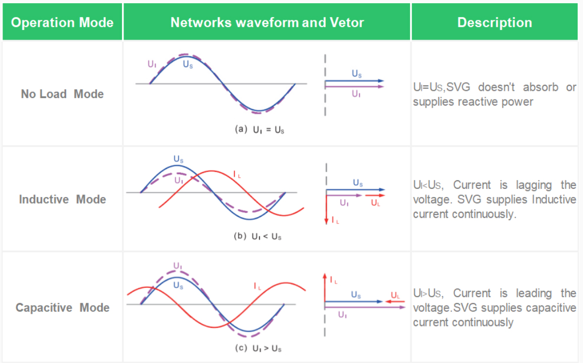
and a coupling transformer. - The VSC generates an AC voltage in phase with the grid but with adjustable magnitude.
- If the output voltage is higher than the grid voltage, it injects
capacitive reactive power (leading). - If the output voltage is lower, it absorbs inductive reactive power
(lagging).
- If the output voltage is higher than the grid voltage, it injects
- The DC capacitor provides the necessary energy storage for the converter.
Key Features of STATCOM
- Reactive Power Compensation
- Generates or absorbs reactive power (VARs) dynamically to
maintain voltage stability. - Unlike traditional SVCs (Static VAR Compensators), STATCOMs use
voltage-source converters (VSCs) for smoother and faster response.
- Generates or absorbs reactive power (VARs) dynamically to
- Voltage Regulation
- Maintains bus voltage at a desired level by injecting or
absorbing reactive power. - Helps mitigate voltage sags, swells, and flicker.
- Maintains bus voltage at a desired level by injecting or
- Dynamic Performance
- Faster response compared to mechanical switches and
thyristor-based compensators (response time in milliseconds). - Effective in damping power oscillations and improving
transient stability.
- Faster response compared to mechanical switches and
- No Need for Large Capacitors / Reactors
- Uses DC capacitors and power electronics (IGBTs/GTOs)
instead of bulky passive components.
- Uses DC capacitors and power electronics (IGBTs/GTOs)
- Black Start Capability
- Some STATCOMs can help restore power in case of a blackout
by providing reactive power support.
- Some STATCOMs can help restore power in case of a blackout
Advantages of STATCOM Over SVC (Static VAR Compensator)
STATCOMs (Static Synchronous Compensators) and
SVCs (Static VAR Compensators) both provide reactive power compensation,
but STATCOMs offer
superior performance in modern power systems. Below is a detailed comparison:
1. Faster Dynamic Response
| Device | Response Time | Implications |
|---|---|---|
| STATCOM | < 1 cycle (5–10 ms) | Better for transient stability, flicker mitigation, and rapid voltage control. |
| SVC (TCR/TSC) | 2–4 cycles (40–100 ms) | Slower due to thyristor switching delays. |
☑ STATCOM wins → Essential for wind/solar farms, HVDC links, and weak grids needing ultra-fast corrections.
2. Better Low-Voltage Performance
| Device | Behavior During Voltage Dips |
|---|---|
| STATCOM | Maintains full reactive current even at very low voltages (down to 0.2 pu). |
| SVC (TCR/TSC) | Reactive power output drops with voltage² (Q = V²/X). |
☑ STATCOM wins → Critical for fault ride-through (FRT) in renewables and preventing blackouts.
3. Smaller Footprint & No Passive Components
| Device | Components | Space Requirement |
|---|---|---|
| STATCOM | Voltage-Source Converter (VSC) + DC Capacitor | Compact (30–50% smaller than SVC). |
| SVC (TCR/TSC) | Thyristor-Controlled Reactors (TCR) + Capacitor Banks | Bulky (large reactors & capacitor banks needed). |
☑ STATCOM wins → Ideal for urban substations, offshore platforms, and mobile installations.
4. Lower Harmonics & No Resonance Risk
| Device | Harmonic Generation | Filter Requirements |
|---|---|---|
| STATCOM | Low (PWM-controlled, <3% THD) | Minimal filtering needed. |
| SVC (TCR/TSC) | High (5th, 7th Harmonics) | Requires bulky filters. |
☑ STATCOM wins → Reduces filter costs and avoids resonance issues with grid impedance.
5. No Need for Step-Up Transformers (in some cases)
- STATCOM can be designed for direct medium-voltage (MV) connection (e.g., 11–33 kV).
- SVC often requires additional step-up transformers for MV/HV grids.
☑ STATCOM wins → Lower equipment costs & losses.
6. Bidirectional Reactive Power (No Switching Lag)
| Device | Reactive Power Transition |
|---|---|
| STATCOM | Seamless (Continuous Control) – No delay between capacitive and inductive modes. |
| SVC (TCR/TSC) | Step-wise (TSC switching delays) – Limited by capacitor bank sizes. |
☑ STATCOM wins → Smoother voltage regulation and better grid stability.
7. Higher Efficiency at Partial Loads
- STATCOM has lower losses (~1–2%) compared to SVC (2–4%), especially at low loads.
- SVC suffers from fixed reactor losses even when idle.
☑ STATCOM wins → Better for energy savings in variable-load systems.
Data Sheet
Here are the detailed technical specifications for a Medium Voltage STATCOM system,
covering key parameters required for procurement, design, and deployment.
Technical Specifications
General Parameters
| Parameters | Specifications |
|---|---|
| Rated Voltage | 3.3kV ~ 35kV (3.3kV / 6.6kV / 11kV / 15kV / 20kV / 25kV / 33kV / 35kV) ±10% |
| Rated Reactive Power | 1MVAr ~ 100MVAr |
| Response Time | No More Than 10ms |
| Cooling System | Air-Cooled or Liquid-Cooled System |
| Control Modes | Voltage Regulation, PF Correction, VAR Control |
| Communication Protocol | IEC 61850, Modbus, DNP3, SCADA Integration |
Electrical Characteristics
| Voltage Operation Range | 0.8 pu to 1.2 pu |
| Frequency Range | 47–52 Hz or 57–62 Hz |
| Harmonic Distortion (THD) | <3% (IEEE 519 Compliant) |
| Overload Capacity | 1.1 Times Continuous Operation (Alarm After 3 Minutes) 1.2 Times Trip After 1 Minute 1.3 Times Trip Instantaneously |
Mechanical Design
| Enclosure | Indoor Type or Outdoor Containerized Type |
| IP Rating | IP30 (Indoor), IP54 (Outdoor) |
| Cooling System | Air-Cooled or Liquid-Cooled System |
Protection & Safety Features
- Overcurrent, Overvoltage, Undervoltage Protection
- Short-Circuit Withstand Capability (1 Second)
- Redundant Control Systems (N+1 Configuration)
- Fire Suppression System (For Liquid-Cooled Units)
Control System
- Digital Controller (DSP / FPGA-Based)
- Real-Time Monitoring (Voltage, Current, VAR Flow)
- Auto-Tuning Algorithms for Dynamic Response
Auxiliary Power Supply
400Vac, 220Vdc, 110Vdc
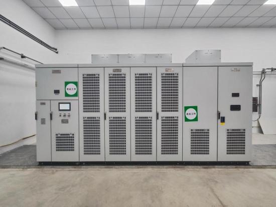
High Voltage Dynamic Compensation (SVG / STATCOM) in Power Distribution Systems
1. Overview of the Project
In metallurgical enterprises, the power distribution system often operates
with a lagging power factor and frequently changing reactive and active loads.
Large fluctuations and instability of reactive current can cause voltage
fluctuations in the system, seriously affecting the safe operation of the
power grid and connected equipment.
When residential loads are connected to the same power grid, system voltage
fluctuations can lead to light flickering and interference with motors and
other electrical equipment.
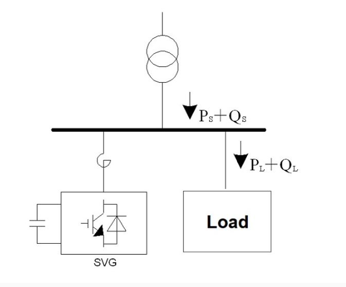
The use of a Static VAR Generator (SVG / STATCOM) in the
distribution system effectively overcomes these issues by providing transient
reactive power whenever required, stabilizing the power supply system and
improving overall power quality.
The system reduces reactive current flow, lowers transmission losses,
improves transformer utilization, increases power factor, and significantly
reduces operating costs.
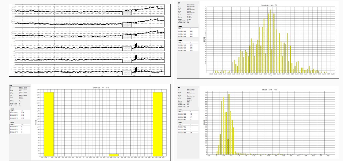
According to the project requirements, the total compensation capacity of
Section I busbar is set at 2MVAr. The SVG/STATCOM is connected
to the 11kV busbar through a high-voltage switch cabinet.
The device continuously tracks power quality changes and rapidly adjusts
reactive power output according to system requirements.
The compensation range can be continuously adjusted from
0 to 2MVAr, ensuring that power factor and harmonic current
remain within national standard requirements.
Similarly, Section II busbar utilizes a 3MVAr SVG/STATCOM
system connected to the same 11kV busbar. The system achieves smooth and
rapid compensation from 0 to 3MVAr.
2. Power Quality Problems of the Project
Power systems supply both active power (P) and reactive power (Q). If
sufficient reactive power compensation is unavailable, several problems arise:
- Reactive power must be transmitted from remote locations.
- Reactive power impacts local and upstream power grid quality.
- Load imbalance and harmonics degrade overall power quality.
Therefore, reactive power compensation, harmonic suppression, and load
balancing are essential for improving load-carrying capacity and ensuring
stable grid operation.
3. SVG / STATCOM for Reactive Power Compensation, Harmonic Filtering & Voltage Support
3.1 Design Targets
- Maintain power factor at 0.95 and above (adjustable).
- Stabilize system voltage.
- Harmonic current complies with national standards.
- Dynamic compensation output current THD ≤ 3%.
- Automatic reactive power tracking according to grid changes.
- Dynamic compensation response time ≤ 5ms.
- Short-term overload capability up to 1.2 times rated capacity.
- Complete protection functions.
- User-friendly HMI interface.
- Remote monitoring and operational data recording.
3.2 Technical Requirements for SVG / STATCOM
- Output Capacity
Uses bus power factor or bus voltage as control targets with smooth
compensation adjustment from 0 to 4MVAr. - Response Time
Dynamically tracks voltage changes and adjusts reactive output with
response time ≤ 5ms. - Overload Capacity
Continuous overload capability of 110% rated capacity. - Cooling Method
Advanced air-cooling technology ensuring reliable operation. - Harmonic Voltage
Harmonic voltage distortion at PCC complies with applicable standards. - Harmonic Current
Harmonic current injection at PCC remains within standard limits. - Three-Phase Voltage Imbalance
Voltage imbalance ≤ 2%. - Voltage Fluctuation
Bus voltage fluctuation ≤ 2%. - Power Factor
Monthly average power factor ≥ 0.95 under normal operating conditions. - Input Voltage Range
90% to 115% of rated voltage. - Input Frequency Range
48Hz to 51Hz. - Low Voltage Ride-Through
Meets applicable LVRT requirements.
3.3 SVG Device Operation Scheme Effect
- The device collects three-phase current signals from the 11kV busbar
and continuously monitors grid power factor and voltage conditions. - When voltage is selected as the control target, the SVG automatically
regulates reactive power output according to user-defined settings. - Power factor control periods and voltage control modes can be freely
configured according to operational requirements.